 QIDAMT
Copper Strip C11000: Temper, Width and Transformer Winding
Copper Strip C11000: Temper, Width and Transformer Winding
Copper strip is a flat rolled copper product, supplied in coils, with a thickness between roughly 0.05 mm and 3.0 mm and a width that can run from a few millimetres to more than 600 mm. It is distinguished from copper sheet and copper plate by thickness and by the way it is handled: strip is thin enough to coil, to slit, to stamp, and to wind, and it is bought by temper, by width and by edge condition rather than by area.
C11000, also called electrolytic tough pitch copper, is the workhorse grade. It is at least 99.90 percent copper, it conducts at about 101 percent IACS in the annealed condition, and it is available in a wide range of tempers and widths at a cost that no other high-conductivity material can match. This article deals with C11000 strip only, with emphasis on one demanding application, transformer winding foil, where a burr of a few hundredths of a millimetre or a temper that is one step too hard can turn a finished coil into scrap.
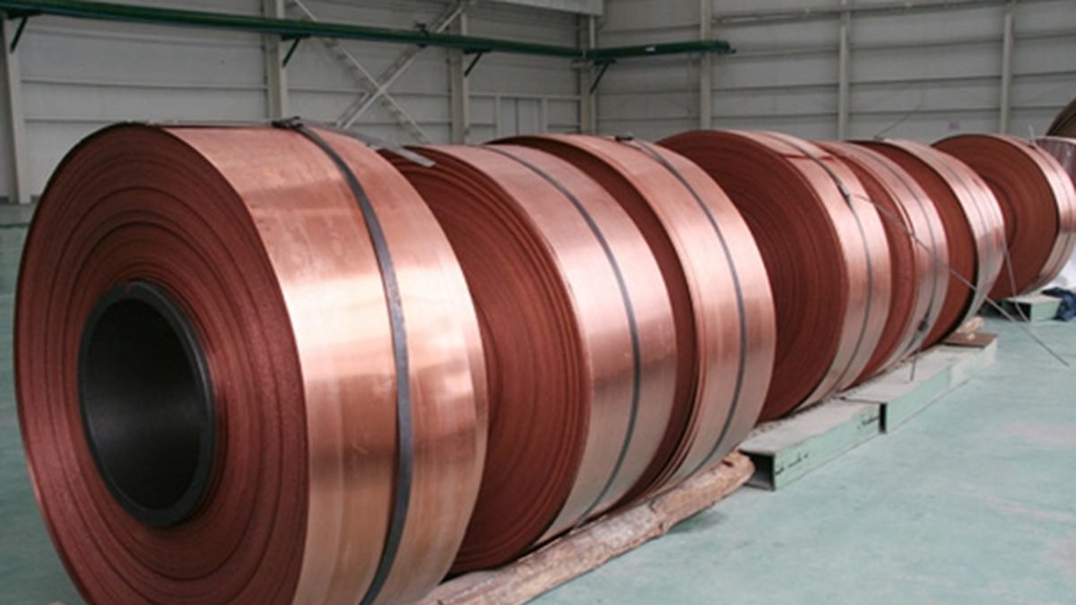
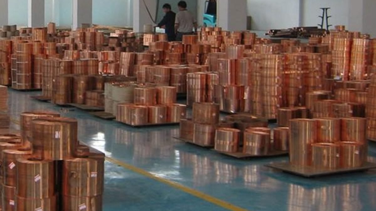
The photographs show copper strip coils stored in a warehouse and a row of wide strip coils on a production floor. The colour is the characteristic salmon red of tough pitch copper; the surface is clean and free of the dark oxide patches and emulsion stains that indicate poor annealing or poor coil handling.
1. What Copper Strip Is and What It Is Used For
Strip is produced by continuous casting and rolling, or by hot rolling a slab and then cold rolling to gauge. The cold rolling passes reduce thickness, increase hardness and improve dimensional control; between passes the strip is annealed to restore ductility. The final pass and the final anneal decide the temper, the grain size and the surface. Slitting then cuts the wide coil into the ordered widths, and the quality of that slitting decides the burr and the camber.
The largest single use of C11000 strip is electrical conduction. Transformer foil windings, busbar of small cross section, connector shells, fuse elements, switchgear components, earthing strip and battery tabs all consume strip in coil form. The second group of uses is thermal: heat exchanger fins, induction heating coils, and heat sinks, where the combination of conductivity and ductility allows a shape to be formed and then soldered or brazed. The third group is architectural and decorative: roofing, flashing, gutters, and interior finishes, where the material is chosen for colour and for the patina it develops.
Each of these uses asks for a different property. A transformer foil needs a soft temper, an extremely clean surface, a controlled burr and a width that matches the winding window to within a fraction of a millimetre. A stamped connector needs a half-hard temper so that it retains its shape after forming. A roofing strip needs a soft temper and a fully annealed grain structure so that it can be bent and folded on site without cracking. A single grade, C11000, covers all three, which is why the temper and the edge condition are specified separately from the alloy.
The reason C11000 dominates is conductivity. At 101 percent IACS in the annealed condition, its resistivity is about 0.01724 Ω·mm²/m at 20 °C. Silver is marginally better and far more expensive; aluminium is cheaper per kilogram but needs about 1.6 times the cross section for the same resistance and is much harder to joint reliably. For a winding that has to fit into a fixed window, the copper cross section is the smallest that will carry the current, and that is the whole argument.
2. Grade and Chemical Composition
C11000 is defined by a minimum copper content of 99.90 percent, with oxygen deliberately present at 0.02 to 0.05 percent. The oxygen is not a impurity in the sense of a defect; it is a controlled addition that reacts with residual impurities during casting and improves the fluidity and the conductivity of the cast bar. That is why the grade is called tough pitch: the metal is neither fully deoxidised nor oxygen-free, and it is tough rather than brittle.
The residual elements that matter most are bismuth, selenium, tellurium, arsenic and antimony. These elements are almost insoluble in copper and they embrittle the grain boundaries, which shows up as cracking during rolling or during bending. The standard limits them to a few parts per million. Sulphur and lead are held low for the same reason. Silver, which is fully soluble and harmless, is not limited, and a high silver content actually improves conductivity slightly.
| Element | C11000 requirement | Effect if out of specification |
|---|---|---|
| Copper | 99.90 % min | conductivity falls, hardness rises |
| Oxygen | 0.02 to 0.05 % | too low: casting problems; too high: blistering on heating |
| Bismuth | 0.0005 % max | hot shortness, edge cracking |
| Selenium and tellurium | 0.0003 % max each | brittle grain boundaries |
| Arsenic and antimony | low, typically 0.0005 % max | loss of conductivity, cracking |
| Lead, sulphur, iron | low, typically 0.001 to 0.005 % | surface defects, reduced ductility |
| Silver | not limited | harmless, slightly improves conductivity |
The oxygen content has a practical consequence that is often missed in specifications. Tough pitch copper that is heated above about 600 °C in a reducing atmosphere, or in the presence of hydrogen, can suffer hydrogen embrittlement: the hydrogen reacts with the dispersed copper oxide to form steam at the grain boundaries, and the metal blisters or cracks. This matters for brazing furnaces, for hydrogen-cooled equipment, and for vacuum casting processes, and it is the reason oxygen-free copper grades are specified for those applications. For an oil-immersed transformer wound at room temperature, C11000 is perfectly suitable. For a cast resin transformer that is vacuum cast and oven cured, the oxide-free grade is the safer choice.
There is also a hydrogen embrittlement test that is worth quoting on a purchase order when the strip will be brazed or furnace processed: a sample is heated in hydrogen and then bent, and the absence of cracks is the acceptance criterion. A supplier who cannot run this test is not a supplier for critical brazing stock.
3. Tempers and Mechanical Properties
Temper is the amount of cold work left in the strip after the final anneal. Full annealed strip has a low strength and a high elongation; hard strip has a high strength and almost no elongation. Between them sit quarter-hard and half-hard, which are produced by cold reducing annealed strip by a controlled percentage. The temper is not decorative: a transformer winding needs a soft strip so that it can be wound tight without cracking and so that it can be bent around the corners of the winding window, while a stamped connector needs a harder strip so that the finished part does not deform in service.
| Temper | Tensile strength | Yield strength | Elongation | Conductivity |
|---|---|---|---|---|
| Annealed (soft, O) | 195 to 245 MPa | about 55 to 100 MPa | 30 to 45 % | about 101 % IACS |
| Quarter hard | 245 to 290 MPa | about 150 to 200 MPa | 20 to 30 % | about 100.5 % IACS |
| Half hard | 290 to 340 MPa | about 220 to 270 MPa | 10 to 20 % | about 100 % IACS |
| Hard | 340 to 400 MPa | about 280 to 330 MPa | 3 to 10 % | about 99 % IACS |
The figures above are typical ranges for strip in the thickness range used in electrical work; the exact acceptance values come from the standard and from the mill certificate. The point to carry into a specification is that conductivity and temper trade against each other. Cold work raises strength and lowers conductivity by a small amount, and annealing restores conductivity but removes strength. A winding specification that demands both full hard temper and 101 percent IACS is asking for two mutually exclusive things.
Grain size is the second mechanical variable. A fully annealed strip with a fine, uniform grain bends and winds well; a strip with an coarse or mixed grain structure will show orange peel on a formed edge and will crack at tight bend radii. For deep-drawn or severely formed parts, the grain size is specified along with the temper, and the mill’s anneal practice has to be matched to the finished part.
4. Thickness, Width, Edge and Tolerance
The dimensional specification of strip is more detailed than that of sheet because strip is processed in automatic machinery. Thickness, width, camber, burr height, coil internal diameter, coil weight and edge condition all matter, and each has its own tolerance.
| Parameter | Typical commercial range | Tolerance commonly quoted |
|---|---|---|
| Thickness | 0.05 to 3.0 mm | ± 0.01 to ± 0.05 mm depending on gauge |
| Width | 3 to 620 mm slit | ± 0.20 mm, tighter by agreement |
| Camber | measured over 1 m | 2 mm max, 1 mm for winding foil |
| Burr height | slit edge | 0.05 mm max, 0.02 mm for foil windings |
| Coil internal diameter | 300, 400, 500 mm | ± 5 mm |
| Coil weight | 50 to 1,000 kg | ± 5 % |
| Length | by weight or by metres | ± 0.5 % on measured length |
| Edge condition | slit, rolled, deburred, rounded | by drawing or sample |
Burr is the parameter that separates a general-purpose strip from a winding strip. Slitting shears the metal, and a shear always leaves a burr on one side. The burr is a sharp ridge of copper standing above the surface, and in a foil winding it acts as a point load on the interlayer insulation. A 0.05 mm burr under a 0.05 mm insulation film is a short circuit waiting for the first thermal cycle. Winding foil is therefore ordered with a burr limit, usually 0.02 mm or less, and often with a rounded or deburred edge produced by a separate edge-forming pass.
Camber is the second hidden parameter. A coil that curves along its length will not track straight through a slitting or winding machine; it will wander, and the wandering produces a winding with edges that step in and out. Camber of 2 mm over a metre is acceptable for general stamping but not for a foil winding, where 1 mm or less is the usual requirement.
Surface condition belongs in the dimensional specification as well. Winding foil should be free of oxide discolouration, emulsion residue, water stains and fingerprints, because these are all either insulating layers or corrosion initiation points. A strip that is bright and clean will accept an insulation coating evenly; a strip with rolled-in oxide will not. Where the foil is supplied pre-coated with a bonding varnish, the coating thickness and the cure state are part of the specification, and the coating has to survive the winding tension without cracking.
5. How C11000 Strip Is Made
The modern route is continuous casting and rolling. Cathode copper is melted in a shaft furnace, the melt is oxidised to the target oxygen content, and the metal is cast into a bar through a moving mould. The bar is immediately hot rolled to a continuous strip, then pickled to remove oxide, then cold rolled in a tandem mill and annealed, either in a batch furnace or in a continuous annealing line. The final cold pass sets the temper and the gauge, and slitting sets the width.
The alternative route is to cast a slab, hot roll it on a reversing mill, and then cold roll and anneal in the same way. Both routes can produce good strip; the continuous route has better dimensional consistency along the coil, which matters for automatic winding and stamping.
The two process steps that most affect the delivered quality are annealing and slitting. Annealing controls grain size, temper and surface; a furnace that is running slightly hot produces a soft strip with a coarse grain and a dull surface, and a furnace that is running cold leaves the strip hard and springy. Slitting controls width, camber and burr; a worn slitter produces a burr that grows through the coil, and a misaligned slitter produces camber. A mill that measures these two steps in process, rather than inspecting at the end, is the mill to buy from.
Packaging is part of the product. Copper strip is soft, and a coil that is dropped or stood on edge will carry a flat spot that feeds badly and can break at the crease. Coils are normally supplied eye-to-the-sky on a pallet, strapped, wrapped in VCI paper or film, and edge-protected with corner boards. For export by sea, the wrap has to be moisture-barrier, because a coil that absorbs humidity in transit arrives with a green-tinted surface that has to be stripped before use.
6. C11000 Strip in Transformer Winding
A foil-wound transformer replaces a round wire winding with a sheet of copper whose width equals the winding height. The foil is wound edge-on, with an insulation layer between turns, so the conductor fills the winding window far more completely than round wire can. The result is a lower leakage reactance, better heat transfer from the conductor to the insulation, a mechanically stiffer winding, and a much simpler winding process.
Four material decisions determine whether the foil works.
Width. The foil width is the winding height, less the end insulation and any margin needed for the edge radii. It is normally specified to plus or minus 0.5 mm, and the coil must be slit to that width with camber controlled. A foil that is 2 mm narrow leaves a gap at the winding end where the insulation has no conductor behind it; a foil that is 2 mm wide fouls the end block. Both are rejects.
Thickness. Low-voltage foil windings commonly use 0.2 to 1.0 mm. Thickness is set by current density, by the number of turns that fit in the window, and by the eddy current loss at the operating frequency. At 50 or 60 Hz the skin depth in copper is about 9 mm, so a foil of 1 mm carries current almost uniformly; at higher frequencies the foil has to be thinner, and the design becomes a compromise between conduction and eddy loss.
Temper. Winding foil is normally supplied annealed. A soft foil conforms to the mandrel and to the corners of the window without springback, and it does not crack at the inside radius of the first turn. Half-hard foil winds with more tension but stores elastic energy, and a winding that is under tension can relax after impregnation and loosen. For a foil winding, annealed is the default and hard temper is a mistake.
Edge quality. This is where most winding failures begin. A burr on the foil edge punctures the interlayer insulation during winding or during the thermal expansion of the first load cycle, and the result is a turn-to-turn short. The requirement is a burr limit, a rounded edge, and an inspection that actually measures the burr rather than looking at the coil. A foil with a 0.02 mm burr and a 0.05 mm insulation film is a design that works; the same foil with a 0.08 mm burr is a design that fails in the field.
The winding process itself has requirements that the strip supplier can support. Winding tension is kept low and controlled, typically a few hundred newtons for a foil of 0.5 mm, so that the foil does not stretch or wrinkle. The foil is guided by edge guides that must not shave the edge; a badly set guide produces a continuous curl of copper that ends up inside the winding. The insulation is fed at the same time, with a small overlap beyond the foil edge so that the burr cannot reach the next turn. After winding, the coil is compressed, clamped and dried, and the foil ends are welded to the busbar.
The end connection is a materials problem in its own right. Foil ends are usually welded by TIG, by ultrasonic or by resistance welding, and the weld has to be full-penetration without overheating the adjacent insulation. C11000 welds readily, but the tough pitch oxygen content can cause porosity in a TIG weld if the pool is not shielded well. For critical joints, the foil end is brazed or soldered with a silver-bearing filler, and the flux residue is cleaned before impregnation.
7. Selection Rules
Start from the current and the window. Calculate the required copper cross section from the current density that the cooling design allows, then choose the foil thickness and width that fit the window with the insulation. Do not choose the thickness first and then try to make the thermal design work.
Specify the temper that matches the forming operation. Annealed for winding, bending and deep forming; half-hard for stamping and for parts that must hold shape; hard only where the part is flat and fully supported. A temper that is one step too hard is a cracking problem that no tooling adjustment will fix.
Specify conductivity, not just alloy. C11000 is a composition, not a guarantee of conductivity. A certificate should state the measured conductivity or resistivity, and the acceptance value should be written into the purchase order. Recycled or off-spec heat can meet the composition and miss the conductivity.
Specify burr and camber for any automatic process. Stamping, winding and slitting all depend on an edge that is straight and clean. If the drawing does not state a burr limit, the mill will supply a commercial burr, and the process will suffer.
Match the oxygen grade to the thermal process. Oil-immersed and dry-type windings that are not furnace brazed can use C11000. Vacuum-cast resin, hydrogen-brazed assemblies and high-temperature furnace cycles need oxygen-free copper, and the purchase order should say so.
Check the coil build-up for your machine. Internal diameter, coil weight and coil width have to match the payoff and the winder. A 500 mm bore coil on a 300 mm mandrel is unusable, and a one-tonne coil on a machine rated for 300 kg is a safety problem.
8. Common Mistakes
Buying strip by thickness and alloy only. Two coils of C11000 with the same thickness can differ in temper, burr, camber and surface, and only one of them will wind.
Using ETP copper for a vacuum casting. The dispersed oxide can blister or crack under vacuum and heat. Use oxygen-free copper and put the hydrogen embrittlement test on the order.
Ignoring burr. The most common cause of turn-to-turn failure in foil windings is a burr that punctured the interlayer film. Specify 0.02 mm and measure it.
Winding with hard temper. Hard foil springs back, does not conform to the window corners, and can crack at the inner radius. Annealed is the winding temper.
Storing coils on the floor. Moisture and floor contact produce green stains and edge corrosion. Store on racks, wrapped, in a dry area.
Cutting foil with a shear and using the cut edge as wound. A guillotine cut leaves a burr that is worse than a slit edge. Deburr the cut edge or use a proper slitting service.
Assuming 100 percent IACS from the alloy name. Conductivity is a measured property. Ask for the test value on the certificate.
Mixing tempers in one winding. A coil wound from two coils of different temper has uneven tension and can relax unevenly after drying. Keep one temper per winding.
Welding the foil end without protecting the insulation. The heat sink of a copper foil is large, and the adjacent film is thin. Use a chill block and a qualified procedure.
Ignoring thermal expansion in the design. Copper expands more than the insulation system and more than the core. A foil winding that is clamped too tightly at room temperature can be loose at operating temperature, and vice versa; the clamping design has to account for it.
9. Frequently Asked Questions
What is the difference between C11000 strip and C10200 strip? C10200 is oxygen-free copper with essentially no residual oxygen, used for vacuum, hydrogen and high-frequency service. C11000 is tough pitch with 0.02 to 0.05 percent oxygen, which is standard for general electrical and thermal work and is cheaper.
Can C11000 strip be soldered? Yes, readily, with a rosin or mildly activated flux and a tin-lead or lead-free solder. The surface must be clean and oxide-free, and the flux residue must be removed if the part will be encapsulated.
Can it be welded? Yes. TIG, MIG, resistance and ultrasonic welding are all used. TIG welding of tough pitch copper can show porosity from the oxygen, so a good shield and a clean surface are essential.
What temper should I order for a stamped connector? Half hard is the usual starting point: it holds shape after forming and still has enough elongation for the bend. Very severe forming may need quarter hard or annealed, and the tool designer should confirm with a trial coil.
How is conductivity measured? By a resistivity test on a sample, expressed in Ω·mm²/m or converted to percent IACS. A four-point resistance measurement on a known length and cross section is the practical shop method.
What is a normal coil weight? From 50 kg for a narrow slit coil to about 1,000 kg for a wide master coil. The order should state the weight range the handling equipment can take.
Does copper strip work harden during slitting? The slit edge is cold worked and slightly harder than the body of the strip, and the burr is work hardened. This is why the edge condition is specified separately from the temper.
What is the maximum width available? Around 600 to 620 mm from a wide cold mill, depending on the mill. Wider requirements are met by welding strip or by using plate.
How should strip be stored? Dry, on racks, wrapped, away from ammonia and sulphur compounds, and with the coil axis vertical. Copper tarnishes quickly in humid air with sulphur, and the tarnish is an insulating layer.
Is C11000 suitable for busbar? Yes, and it is the common choice for small busbar sections. For large sections, copper bar or plate is used; strip is practical up to about 3 mm thickness and moderate width.
Need C11000 copper strip to a winding specification?
Send the thickness, width, temper, burr limit, coil size and the application. We will confirm the conductivity, the edge condition, the packing and the delivery schedule, and quote against the measured specification rather than a nominal alloy name.
Related reading: C11000 copper plate · C11000 copper coil · C12200 copper tube