 QIDAMT
Copper Busbar C11000: Conductivity, Sizing and Jointing
Copper Busbar C11000: Conductivity, Sizing and Jointing
A copper busbar is the part of an electrical assembly that carries current from one component to another without a cable in between. It is specified by conductivity, cross-section, joint design and temperature rise, and it is the component that decides whether a switchgear enclosure runs cool or cooks its own insulation.
This guide covers C11000 electrolytic tough pitch copper busbar: what the grade requires, how to size a bar for a given current, how the joints are made and inspected, how the bar behaves under short-circuit, and the errors that show up as hot spots, loose joints and failed thermographic surveys.
1. Why Copper, and Why C11000
Copper is the practical conductor for busbar because it combines high conductivity with enough strength to be self-supporting. Aluminium is lighter and cheaper per kilogram, but it needs about 60 % more cross-section for the same current, it forms an insulating oxide that must be broken before every joint, and it creeps under bolted pressure. Silver has better conductivity and costs many times more. Copper is the compromise that industry has settled on.
Among copper grades, C11000 ETP is the electrical standard. It is cathode copper with controlled oxygen, 99.90 % minimum purity, and a conductivity of 100–101.5 % IACS. The oxygen content does not affect conductivity, and it does not matter for a bolted or clamped joint. It matters if the bar is welded, which is why welded busbar assemblies sometimes specify C12200 or a deoxidized grade instead.
| Property | C11000 value | Design significance |
|---|---|---|
| Copper content | 99.90 % min | Conductivity and solderability |
| Conductivity | 100–101.5 % IACS | Cross-section for a given current |
| Resistivity at 20 °C | 0.01724 Ω·mm²/m | Voltage drop and losses |
| Thermal conductivity | 385–395 W/(m·K) | Heat spreading along the bar |
| Density | 8.90 g/cm³ | Weight and support loading |
| Melting point | 1083 °C | Short-circuit and fire behaviour |
| Coefficient of expansion | 17 × 10⁻⁶ /K | Expansion allowance in long runs |
A word on “100 % IACS”: the standard defines 100 % IACS as a resistivity of 0.017241 Ω·mm²/m at 20 °C. C11000 typically tests slightly above 100 %, which is why the specification says “100 % IACS minimum” rather than a fixed value. Conductivity should be stated on the mill certificate, measured on the finished bar, not only on the cast billet.
2. Sizing a Busbar
Busbar sizing is a thermal problem before it is an electrical one. The bar has resistance, the resistance produces heat, and the heat must leave the bar by convection and radiation without pushing the temperature above the limit set by the insulation, the enclosure and the standard. The current that satisfies that balance is the bar’s rating.
A first approximation uses a current density of 2.0–3.5 A/mm² for a single bar in still air at a 30–40 K rise, and 3.5–5 A/mm² where there is forced ventilation or the bar is in a well-ventilated enclosure. Those figures are starting points, not ratings. The real rating depends on bar orientation, spacing to the next bar, enclosure size, nearby heat sources and altitude, and it must be verified against the switchgear standard and the enclosure thermal test.
| Bar section | Area | Weight | Typical current, single bar, still air |
|---|---|---|---|
| 20 × 5 mm | 100 mm² | 0.89 kg/m | 200–300 A |
| 30 × 5 mm | 150 mm² | 1.34 kg/m | 280–400 A |
| 40 × 5 mm | 200 mm² | 1.78 kg/m | 350–480 A |
| 50 × 10 mm | 500 mm² | 4.45 kg/m | 650–850 A |
| 80 × 10 mm | 800 mm² | 7.12 kg/m | 900–1150 A |
| 100 × 10 mm | 1000 mm² | 8.90 kg/m | 1050–1400 A |
| 120 × 10 mm | 1200 mm² | 10.68 kg/m | 1250–1600 A |
These ranges assume a single bar, natural convection, a rise of roughly 30–40 K, and a bar mounted vertically or horizontally with free air on both faces. A bar in a closed metal enclosure loses a large part of its convection, and the rating falls by 15–25 %. Two bars in parallel do not double the rating either: the current sharing is uneven, and the mutual heating reduces the per-bar rating. Use 80–90 % of twice the single-bar figure as a rough guide, and verify.
At 50 Hz the skin effect in a bar up to about 20 mm thick is small, and the AC resistance is close to the DC value. Above that, or at high harmonic content, the current crowds toward the surface and the effective resistance rises. Inverter-driven loads and 400 Hz systems need the AC resistance calculated, not assumed.
3. Short-Circuit Withstand
A busbar must survive a short circuit for the time the protection takes to clear it. The mechanical part is the peak electromagnetic force between bars, which is enormous: two parallel bars carrying a fault current attract or repel each other with a force proportional to the square of the current and inversely proportional to the spacing. A 25 kA peak across a 20 mm gap produces a force that will bend a lightly supported bar.
The thermal part is the I²t energy. The bar must absorb the fault energy without annealing, melting or losing its joint pressure. The check is against the switchgear standard’s specified withstand current and duration, usually 1 s, and against the manufacturer’s published I²t data for the bar and the joint. Do not compute it from the adiabatic formula alone: the joints and the supports are the weak points, not the bar.
Practical measures: support the bars at close intervals near the ends and at the middle of long spans, use insulating barriers between phases where the fault level is high, and check the joint hardware for the specified grade, because a mild steel bolt in a high-current joint will heat and loosen.
4. Temper and Mechanical Properties
| Temper | Tensile | Yield | Elongation | Typical use |
|---|---|---|---|---|
| Soft O60 | 220–260 MPa | 60–90 MPa | 35–45 % | Formed and bent bars |
| Half hard H02 | 260–310 MPa | 180–240 MPa | 15–25 % | General busbar |
| Hard H04 | 310–380 MPa | 260–330 MPa | 3–10 % | Machined bars, high stiffness |
Hard temper gives a stiffer bar that resists short-circuit bending, but it is difficult to bend on site and prone to cracking at a tight radius. Half hard is the usual supply for switchgear and panel work: enough stiffness for the fault level, enough ductility to bend. Where the bar will be bent into a complex shape, specify soft temper and accept the lower stiffness, or design the support to compensate.
5. Dimensions and Tolerances
| Dimension | Range | Tolerance | Note |
|---|---|---|---|
| Thickness | 2–30 mm | ±0.10 mm below 5 mm; ±2 % above | Affects resistance and joint area |
| Width | 10–200 mm | ±0.5 mm | Affects surface area and fit |
| Length | Up to 6 m | ±2 mm | Cut to length on order |
| Straightness | — | 2 mm/m max | Critical for bolted joints |
| Edge radius | R2–R5 | — | Reduces corona and injury risk |
| Twist | — | 1°/m max | Distorts joint contact |
Order the bar with the edges rounded and deburred. A sheared edge leaves a burr that concentrates the electric field, and in medium-voltage equipment that burr is where a corona discharge starts. For low-voltage panel work the burr is mostly a handling hazard, but it also prevents the bars from sitting flat against each other.
6. Jointing
The joint, not the bar, is where a busbar system fails. A bolted joint carries current through the actual metal-to-metal contact spots, which are a small fraction of the apparent area. The design has to keep that contact area stable for the life of the installation.
Surface preparation. Degrease, then brush or abrade the contact faces to remove oxide, then apply a joint compound or a contact grease immediately. Bare, freshly brushed copper re-oxidizes within hours in humid air, and copper oxide is a poor conductor.
Plating. Tin plating is standard for indoor busbar: it prevents oxidation, keeps the contact resistance stable, and is compatible with aluminium joints. Silver plating is used in high-current and medium-voltage joints where the lowest contact resistance is required; it tarnishes in sulphide atmospheres and needs attention. Bare copper is acceptable only in a dry, controlled environment with a joint compound.
Bolting. Use the specified bolt grade, usually grade 8.8 or stainless, with a flat washer and a spring or Belleville washer to maintain pressure through thermal cycling. Tighten to the manufacturer’s torque with a calibrated wrench, and mark the bolts after tightening so that a later inspection can see whether any have moved.
Brazing and welding. Brazed joints are used where a permanent, low-resistance connection is required, and they must be made with the correct filler and flux, then cleaned. Welded joints in C11000 need a deoxidized filler and no hydrogen; a welded busbar joint in ETP copper is a specialist operation and is often better replaced by a bolted or brazed design.
Compression and mechanical lugs. For cable-to-busbar connections, use a compression lug with the correct die and the correct number of crimps, then cover with a heat-shrink boot. A lug crimped with the wrong die looks acceptable and overheats.
7. Installation Rules
Support the bars so that the fault force does not bend them into the next phase. Keep the phase spacing as designed; increasing it reduces the force but increases the loop inductance and the voltage drop. Respect the clearance and creepage distances in the applicable standard, and remember that a bar with a sharp bend has a different field distribution from a straight one.
Allow for expansion. A 3 m copper bar grows about 1.5 mm over a 30 K rise, and a rigidly clamped bar in a rigid frame will either bow or loosen its joint. Use slotted holes or flexible connections at one end of a long run.
Keep the bars away from steel parts that will heat inductively. A steel support bracket close to a high-current bar will warm up and, in the worst case, act as a shorted turn. Use non-magnetic stainless or insulated brackets.
Finally, design for inspection. A thermal imaging survey after commissioning is the standard check, and it only works if the joints are visible and the enclosure can be opened safely. Leave access.
A commissioning sequence that catches most defects: torque-check every joint and mark it, measure the contact resistance of each joint against a reference, run the assembly at full load for two hours, then survey with a thermal imager and compare phase-to-phase temperatures. A phase that runs more than 10 K hotter than its neighbours has a joint problem, a current-sharing problem or a bad connection, and it will not fix itself.
8. Common Mistakes
Sizing on current density alone. The density figure is an approximation. Without the enclosure and spacing, it can under-size a bar by 20 %.
Using C12200 because it is cheaper. Conductivity falls to about 85 % IACS, so the bar needs to be larger for the same rise, and the design may not have the space.
Bolting bare copper without compound. The oxide film raises the joint resistance, the joint runs hot, the heat oxidizes more copper, and the failure accelerates.
Over-tightening to “make sure”. Excessive torque crushes the bar and the washer, reduces the contact area, and can crack the insulator.
Mixing copper and aluminium without a transition. The joint corrodes in the presence of moisture, and the resistance rises until it fails.
Ignoring the short-circuit force. The steady-state thermal calculation passes and the bars bend on the first fault.
No thermal survey after commissioning. A loose joint is invisible until it fails; a thermal image finds it in an hour.
9. Frequently Asked Questions
Can I use C11000 busbar outdoors? Yes, with a suitable coating or plating. Bare copper outdoors develops a patina and, in polluted air, corrodes at the edges. Tin plating or a paint system is normal for outdoor installations.
What is the difference between a busbar and a busbar terminal? The bar is the conductor; the terminal is the connection point, usually a lug or a clamped joint. The terminal is the part that must be tested for contact resistance.
Is silver plating worth it? At high current and in medium-voltage equipment, yes. In a low-voltage panel, tin plating is adequate and cheaper.
Can busbar be bent on site? Yes, with a proper bender and a soft or half-hard temper. A hard-temper bar bent on a press brake without annealing will crack.
How often should joints be checked? At commissioning, then at each maintenance interval with a thermal image and a torque check on a sample. A joint that has lost 10 % of its torque should be re-made.
What causes a busbar to overheat at one end? Usually a poor joint, a loose bolt or a contact face that was not cleaned. The bar itself is uniform; the heat is at the resistance.
Does the bar need derating at altitude? Yes. Air density falls, convection falls, and the rating drops. Apply the manufacturer’s altitude correction or recalculate.
Can copper busbar be painted? Paint is an insulator and it traps heat unless the coating is thin and rated for the temperature. For appearance or corrosion protection, use a thin anticorrosive coating and derate the bar to allow for the reduced convection.
What is the difference between a busbar and a cable? A busbar is a rigid conductor, sized on heat and short-circuit force, and jointed mechanically. A cable is flexible, insulated and sized on the same thermal basis but with a different installation derating. Busbar is used where the current is high, the run is short and the assembly must be compact.
10. Sourcing Copper Busbar
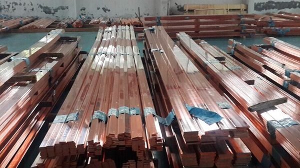
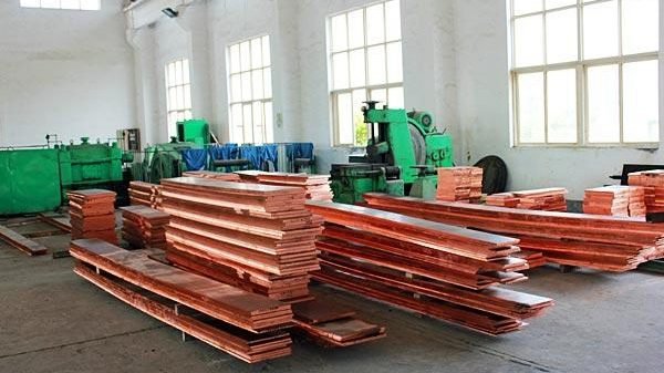
QIDAMT supplies C11000 ETP copper busbar from 2 mm to 30 mm thick, 10 mm to 200 mm wide, cut to length up to 6 m, with rounded and deburred edges, in soft, half-hard and hard temper, with mill certificates stating conductivity and mechanical properties. Bars are packed flat on timber, strapped, and edge-protected for export.
Send the section, length, temper, conductivity requirement and the joint finish (bare, tin plated or silver plated). We will confirm stock and tolerance before quotation.
Need C11000 copper busbar?
Send the section, temper and length for a quotation with conductivity data on the certificate.
Related specifications: C11000 ETP copper plate, C11000 copper coil, and C12200 copper tube.