 진전
Stainless Steel Welded Duct: Plate Thickness, Diameter Range and Leak Testing
A stainless steel welded duct is a cylindrical or conical air or product-contact passage fabricated from stainless plate, rolled to diameter and closed with a longitudinal weld. It is not a purchased standard fitting: it is a fabricated assembly whose quality depends on the plate thickness, the rolling accuracy, the weld procedure and the leak test that proves the seam is closed. This guide sets out how the 304 duct is built, which thickness suits which diameter and pressure, how roundness and squareness are specified, and how a leak test should be written so that it actually means something.
정의, Function and Typical Applications
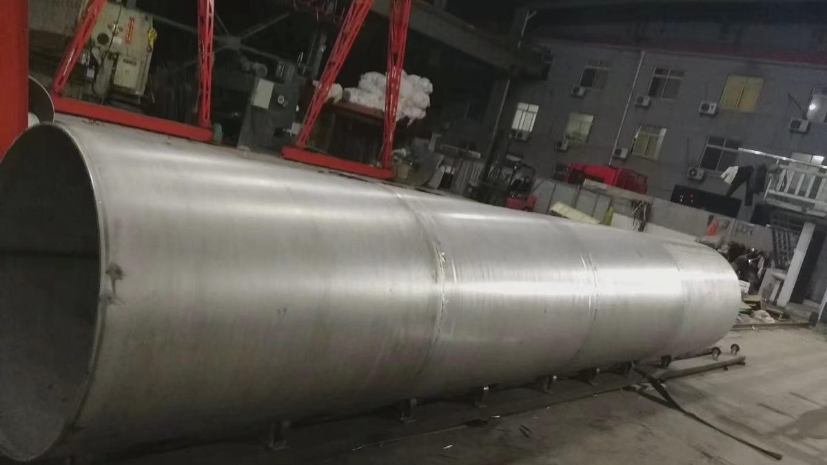
A welded duct is made by cutting a stainless plate to a developed length, rolling it on a three-roll or four-roll machine, closing the longitudinal seam with a weld, and then adding whatever the system needs: flanges, stiffening rings, access doors, branches, or a transition cone. The result is a thin-wall shell that carries air, dust, vapour or a liquid product, often at modest pressure but with a strict requirement for cleanliness or corrosion resistance.
The product appears in four broad families:
- HVAC and process exhaust ducting in food, pharmaceutical and electronics plants, where galvanised steel would corrode or shed particles.
- Dust collection and fume extraction ducting, including cyclone inlets and cone transitions, where abrasion resistance and a smooth bore matter.
- Product-contact piping and chutes in dairy, brewing and chemical plants, where the bore must be cleanable and the weld must be flush and passivated.
- Architectural and marine ventilation, where the duct is visible, exposed to salt air, and often specified in 316L rather than 304.
The distinction from spiral duct is important. Spiral duct is made from a strip wound and locked or welded along a continuous helix, with a fixed set of standard diameters and short lengths. A welded duct is made to a developed length from flat plate, so almost any diameter from about 100 mm 에 2 000 mm is possible, wall thickness can be selected freely, and the seam is a single longitudinal weld that can be inspected, radiographed or leak-tested as one line. That flexibility is what makes welded duct the right choice for cones, transitions, non-standard sizes and pressure service.
Grade and Chemical Composition
The default grade for welded duct is 304 (안에 1.4301). It combines adequate corrosion resistance for indoor air and food service with good forming and welding behaviour, and it is readily available in the thickness range used for ductwork. For chloride-bearing air, coastal installations, or cleaning chemicals containing hypochlorite, 316L is specified instead; the molybdenum addition raises pitting resistance but also raises cost and reduces availability in thin sheet.
| 요소 | 304 범위 (%) | Function in a duct shell | Process consequence |
|---|---|---|---|
| 기음 | ≤ 0.08 | Austenite stability | High C: carbide precipitation at weld, reduced intergranular corrosion resistance |
| Cr | 18.0 – 20.0 | Passive film | Lower Cr: staining and pitting in humid exhaust |
| ~ 안에 | 8.0 – 10.5 | Austenite former | Low Ni: ferrite at weld, magnetic seam |
| 망 | ≤ 2.00 | Austenite former | Balances sulphur |
| 그리고 | ≤ 1.00 | Deoxidation | High Si: weld scale, poor pickling |
| 피 | ≤ 0.045 | 불결 | Hot cracking in the weld |
| 에스 | ≤ 0.030 | 불결 | Sulphide inclusions, pitting initiation |
| N | ≤ 0.10 | 힘 | High N: stronger but less ductile in rolls |
| 철 | 균형 | Matrix | — |
Composition to EN 10088-2 / ASTM A240 for 304 시트; certificate to be checked against the heat number.
Two wire-level concerns carry over to duct plate. Carbon at the top of the range precipitates chromium carbides in the weld heat-affected zone and reduces intergranular corrosion resistance, which is why 304L is often substituted for welded assemblies that will see acid cleaning. Sulphur raises the risk of hot cracking in a full-penetration longitudinal seam, particularly on thicker plate; a mill certificate with S below 0.020 % is a useful selection criterion for 3 mm 이상.
Thickness is the next decision. Duct shells carry little pressure but they must resist handling, support their own weight between hangers, and hold shape during welding. A plate that is too thin buckles when rolled and distorts when the seam cools; a plate that is too thick wastes material and makes the rolling and flanging operations difficult.
Mechanical Properties and Thickness Selection
단련 304 sheet has a tensile strength of about 515–700 MPa, 에이 0.2 % proof stress of about 205 MPa and an elongation of 40 % or more. Those values are generous for ductwork, so the design is normally governed by stiffness and handling rather than by strength. The practical rule is to select thickness from the diameter and the support spacing, then check that the resulting shell can be rolled and welded without buckling.
| Nominal diameter (mm) | Typical plate thickness (mm) | Support spacing (중, 최대) | Typical service |
|---|---|---|---|
| 100 – 300 | 0.8 – 1.0 | 1.5 – 2.0 | Low-pressure exhaust, food service |
| 300 – 600 | 1.0 – 1.5 | 2.0 – 2.5 | General HVAC and fume |
| 600 – 1 000 | 1.5 – 2.0 | 2.5 – 3.0 | Process exhaust, dust collection |
| 1 000 – 1 500 | 2.0 – 3.0 | 3.0 – 4.0 | Cyclone inlets, large transitions |
| 1 500 – 2 000 | 3.0 – 4.0 | 3.0 – 4.0 with rings | Heavy process duct, cones |
Indicative thickness guidance for unpressurised or low-pressure 304 duct; 압력, vacuum and seismic cases require calculation.
For a cone, thickness selection follows the largest diameter, not the small end. A cone rolled from 1.5 mm plate at a 1 200 mm large end will oil-can between the rolls and lose roundness at the open end; the same cone in 2.5 mm holds its shape. The cone also needs a developed length calculated on the neutral axis, and the seam is usually placed on the side, away from the bottom where condensate collects.
Mechanical properties also set the weld procedure. ㅏ 304 weld made with matching 308L filler and a controlled heat input retains most of the parent strength in the annealed condition; a weld made without purge, or with too much heat, produces a heavily oxidised root that is both a corrosion site and a leak path. For thin sheet, the weld is usually autogenous TIG with a backing gas; ~을 위한 3 mm 이상, a V-groove with filler and a purge dam is the normal practice.
지름, Roundness and Squareness Tolerances
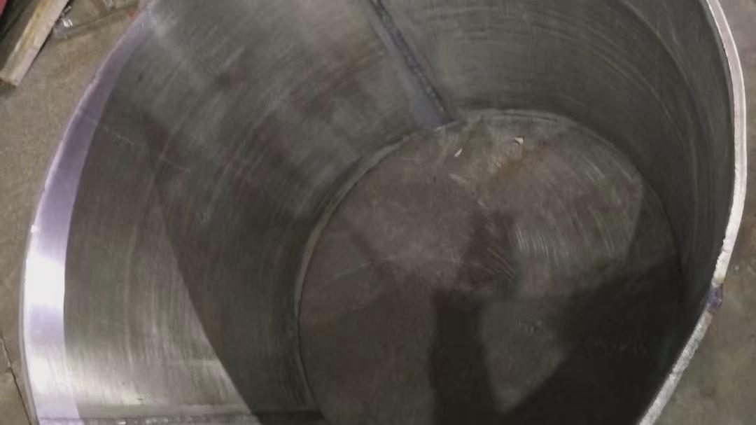
A fabricated duct is measured against a specification, not against a nominal size. 직경 공차, out-of-roundness, straightness and flange squareness are the four dimensions that decide whether the duct will bolt to the next spool and whether the system will leak at the joint.
| 매개변수 | 일반적인 공차 | How it is measured | Effect if exceeded |
|---|---|---|---|
| 외경 | ± 1.0 % of nominal, min ± 1 mm | Circumference tape or calliper at four points | Flange mismatch, gasket cannot seal |
| Out-of-roundness | ≤ 1.0 % of diameter | Max minus min diameter in one section | Oval shell, poor fit at branch |
| 직진도 | ≤ 2 mm/m, 최대 10 mm over length | Feeler gauge on a surface table | Misaligned spool, stress at flange |
| Flange squareness | ≤ 1 mm per 100 mm of diameter | Square against the flange face | Gap around the gasket, leak at bolts |
| 길이 | ± 2 mm for flanged spools | Tape on the finished spool | Gap or interference at the joint |
| Seam alignment | ≤ 1 mm offset, full penetration | Visual and weld gauge | Step in the bore, incomplete fusion |
Typical fabrication tolerances for welded 304 duct; project specifications and the applicable code take precedence.
Out-of-roundness is the parameter most often skipped at goods-in, and it is the one that causes the most field problems. A duct that is 2 % oval will still bolt to a flange, but the gasket is compressed unevenly and the joint weeps under a slight positive pressure. Measuring the diameter at four points around one section with a tape is enough to catch it; a full calliper survey is only needed for critical process duct.
Flange squareness deserves the same attention. A flange welded 2 mm out of square on a 600 mm duct produces a gap that no gasket will close, and the installer will compensate by over-tightening one side, which distorts the flange and creates a leak elsewhere. Specify squareness per 100 mm of diameter and check it with a square and feeler gauge before the flange is fully welded.
Fabrication Sequence and Weld Quality
The fabrication sequence is fixed for a reason: each operation relieves or introduces stress, and the order determines whether the finished duct is round.
- Cut the plate to the developed length, allowing for the weld gap and for shrinkage; shear or plasma cut, then deburr the edges.
- Roll the plate on a three-roll or four-roll machine in several passes, keeping the seam edge parallel; do not attempt a full curvature in one pass.
- Tack the seam at both ends first, then at intervals, checking diameter and roundness before the final weld.
- Weld the longitudinal seam with a qualified procedure, purging the root with argon on the inside; for thin sheet, use a copper backing bar to control the root.
- Stress-relieve or mechanically round the shell after welding, because the seam contraction pulls the section oval.
- Fit and weld flanges, rings and branches, keeping heat input balanced on opposite sides to limit distortion.
- Pickle and passivate the welds and heat tint, then rinse and dry; a wire-brushed weld is not a substitute for pickling.
Weld quality is judged on three things: penetration, oxidation and profile. Full penetration is required for a leak-tight duct, and it is verified by the leak test rather than by appearance. Oxidation on the root is a corrosion site and must be removed by purging during welding or by pickling after; a straw-coloured or blue root is acceptable only if the specification allows it, and a black, sugary root is not. Profile matters for product-contact duct: a convex bead or a sharp undercut traps product and defeats cleaning, so the weld is usually ground flush and blended on the inside.
Distortion control is the fabricator’s real skill. ㅏ 1 000 mm diameter shell with a 2 mm wall contracts about 2–3 mm across the seam when it cools; that is enough to make the section oval by 1 %. Rounding with a hydraulic press or a ring roller after welding, and welding the seam in a sequence that balances heat on both sides, restores roundness. On cones, the small end distorts more than the large end, and a stiffening ring at the small end is often the cheapest way to hold the profile.
Leak Testing and Acceptance
A welded duct that carries air at a slight positive pressure does not need a hydrostatic test, but it does need a leak test that matches the service. The three practical methods are a low-pressure air test with soap solution, a pressure decay test, 그리고, for critical product-contact or vacuum service, a helium leak test.
| Method | Typical test pressure | Acceptance criterion | 다음에 가장 적합 |
|---|---|---|---|
| Air + soap bubble | 10 – 30 kPa | No bubble growth at any seam or flange for 1 분 | General exhaust and HVAC duct |
| Pressure decay | 10 – 50 kPa | Drop ≤ 1 % of test pressure over 10 분 | Shop-assembled spools with gauges |
| Helium vacuum / sniffer | Vacuum or 10 kPa helium | Leak rate ≤ 1 × 10⁻⁶ mbar·L/s | Vacuum, 제약, high-purity |
| Dye penetrant (weld only) | — | No indication on the seam | Weld inspection before assembly |
Test pressures are indicative; the project specification and the applicable pressure-vessel or ductwork code govern.
A soap bubble test is only meaningful if the duct is capped and the pressure is held long enough for a small leak to show. Cap both ends, apply 10–30 kPa, brush the seam and flange with a soap solution, and watch for a minute at each point. A leak that produces a slow-growing bubble is as much a failure as one that blows foam, and the test should be recorded with the pressure, the duration and the location of every repaired point.
Pressure decay is more objective but needs a stable temperature. A duct tested in a cold shop in the morning and re-read in the afternoon will show a pressure change from temperature alone; record the ambient temperature with the gauge reading, or use a differential gauge referenced to a sealed volume. For critical service, the helium test is the only method that quantifies a leak rate, and it must be done before the duct is insulated or lagged, because the insulation hides the leak path.
Installation and Support Rules
- Support the duct at the spacing used in the thickness selection, and never hang a spool from its flange bolts alone.
- Use stainless or isolation-coated hangers; a galvanised hanger in contact with a stainless shell creates a galvanic couple and stains the duct at the contact point.
- Allow for thermal expansion between spools; 에이 10 m stainless run at 80 °C grows about 10 mm, and rigid flanges at both ends will buckle the shell.
- Fit expansion joints or slip joints at long runs, and keep the joint accessible for inspection.
- Do not mix 304 duct with carbon steel supports in a wet environment without isolation; the carbon steel will corrode first, but the stainless will stain.
- Keep the bore free of weld spatter and grinding dust before commissioning; debris in a product duct is a contamination finding, not a cleaning task.
일반적인 실수
- Specifying the diameter without a roundness tolerance. A duct within ± 1 % on diameter can still be 2 % oval and leak at the flange.
- 사용 0.8 mm plate for a 1 200 mm cone because the drawing says “sheet metal”. The shell will oil-can and lose roundness during welding.
- Welding without a purge and calling the black root acceptable. The oxide is a corrosion site and a leak path that the soap test will eventually find.
- Testing with air at 5 kPa and declaring the duct leak-tight. Small leaks need enough pressure and enough dwell time to show.
- Bolting flanges without checking squareness. Over-tightening one side distorts the flange and creates a leak elsewhere.
- Pickling the plate but not the weld. Heat tint is where pitting starts, and it is always at the weld.
자주 묻는 질문
What thickness should a 600 mm stainless duct use?
For unpressurised exhaust or HVAC service, 1.0–1.5 mm 304 is the usual range, with supports at 2.0–2.5 m. For a product-contact duct that will be cleaned or sees slight pressure, 1.5 mm is safer because it holds roundness better and tolerates weld distortion.
Can a welded duct be made in 316L instead of 304?
예, and it should be for coastal air, chloride cleaning or marine service. The fabrication sequence is the same; the welding filler changes to 316L, and the pickling paste must be suitable for molybdenum-bearing steel.
Does a welded duct need a hydrostatic test?
Only if it is designed for liquid service or a pressure rating that the code requires. Air and fume ducting is normally tested with low-pressure air and soap solution or a pressure decay test.
How is a cone developed?
A concentric cone is developed as an annular sector whose radii are the slant heights of the large and small ends and whose angle is set by the circumference of the large end. Add a weld allowance and roll the plate with the seam on the side.
Why does the duct become oval after welding?
The longitudinal weld contracts as it cools, pulling the section in at the seam. Balancing the weld sequence, using a copper backing bar, and rounding after welding control it; a stiffening ring at the open end is the usual remedy on cones.
Is a flush-ground weld required inside a duct?
For product-contact, pharmaceutical or food service, 예: a convex bead or undercut traps product and prevents cleaning. For exhaust ducting, a sound full-penetration weld with a cleaned root is sufficient.
Need a welded 304 duct, cone or transition to a specific diameter?
Send the drawing, 지름, thickness and test requirement; we will quote fabrication and leak testing.
Related flat product for the same project: 304 2B cold-rolled sheet for the duct shell, 그리고 316L 플레이트 where chloride resistance is required.