 EDISTYMINEN
Steel Bridge Railing: Post Spacing, Anchor Design and Coating
Steel Bridge Railing: Post Spacing, Anchor Design and Coating
A bridge railing looks like a simple row of posts and tubes. Structurally it is a safety barrier whose job is to stop a pedestrian, a cyclist or a maintenance worker from falling, and in many bridge designs to guide a vehicle that has already left its lane. The difference between a railing that performs and one that merely looks finished is decided by three things that are invisible in a photograph: how far apart the posts are, how the post base is anchored into the deck, and how the steel is protected against the particular atmosphere of the site.
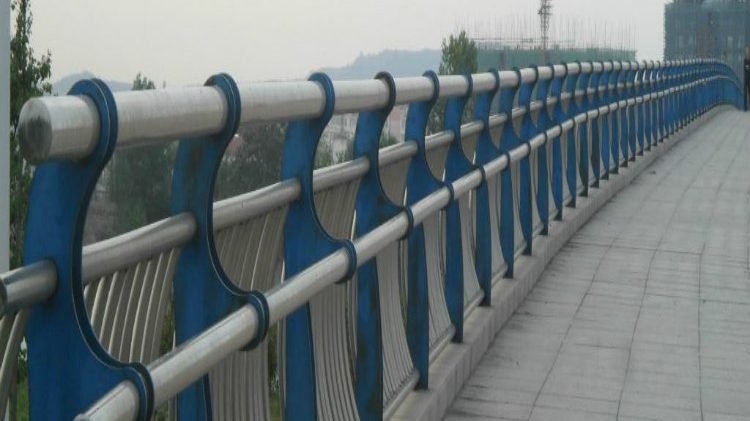
The photographs used here show a completed pedestrian railing on a bridge deck and a stack of fabricated posts with their base plates. Read together, they illustrate the two halves of the problem: the finished line that the public sees, and the fabricated element whose geometry and weld quality determine whether that line stays straight and upright for twenty years.
1. What a Steel Bridge Railing Is, and What It Is Not
A steel bridge railing is a fabricated barrier installed along the edge of a bridge deck, an approach ramp, an overpass or a pedestrian structure. It usually consists of vertical posts at regular intervals, one or more horizontal rails, and infill elements such as vertical bars or a perforated panel. Posts are anchored to the deck through base plates and cast-in or post-installed anchors; rails are connected to posts by welding, bolting or a combination of both.
It is not the same product as a highway W-beam guardrail. A W-beam system is a flexible, crash-tested vehicle barrier made from corrugated steel rail on posts that are designed to yield and redirect a vehicle. A bridge railing for pedestrians is a stiffer, architectural element designed around a horizontal design load and an anti-climb requirement. Some bridges use a combined system: a crash barrier on the carriageway edge and a pedestrian railing on the walkway edge, with the two specified separately. Buying one and installing it in place of the other is a design error, not a commercial one, and it will not survive an inspection.
The applications are easy to list and easy to underestimate. Urban overpasses, river crossings, railway platform edges, industrial walkways, port access bridges, dam crest walkways and temporary long-span footbridges all use this family of product. Each has a different governing load, a different maintenance regime and a different visual expectation, which is why a railing specification that does not name the structure is incomplete.
2. Steel Grades and Section Properties
Most bridge railings in China are fabricated from Q235B or Q355B structural steel. Q235B is adequate for the posts and rails of a pedestrian barrier with modest spans between posts; Q355B is used where post spacing is wide, where the railing is also acting as a vehicle containment element, or where the design calls for a slimmer section at the same strength. The grade must be stated on the drawing and confirmed by mill certificate, because substituting Q235B for Q355B in a section designed around the higher grade reduces the safety margin by roughly a third.
| Omaisuus | Q235B | Q355B | Design consequence |
|---|---|---|---|
| Sadonvoimakkuus, min | 235 MPa | 355 MPa | Sets the post’s bending capacity at the base |
| Vetolujuus | 370 to 500 MPa | 470 to 630 MPa | Governs weld procedure qualification |
| Pidentymä, min | 26 % | 20 % | Both are ductile enough for cold forming of rails |
| Carbon equivalent | noin 0.30 | noin 0.40 | Higher CE means more careful welding and preheat in cold weather |
| Typical use in railing | Posts, rails, infill bars | Long-span posts, vehicle containment, heavy sections | Match the grade to the design load, not to availability |
Section choice follows a small number of standard shapes. Posts are usually square hollow sections of 80 by 80 mm asti 120 by 120 mm with wall thickness from 4 to 8 mm, or round tubes of 89 to 114 mm diameter. Rails are round tubes of 48 to 76 mm, or rectangular hollow sections for a flatter profile. Infill is either vertical bars of 16 to 20 mm at 110 to 130 mm centres, or a perforated panel. The 110 mm gap rule is not decorative: a clear opening that admits a small child’s head but not the shoulders is a well-known entrapment hazard, and most railing codes limit clear gaps accordingly.
| Elementti | Typical size | Governing consideration |
|---|---|---|
| Post section | SHS 100 × 100 × 6 mm, or tube 114 × 4.5 mm | Bending at the base under the design horizontal load |
| Post height | 1100 mm above deck, measured to the top rail centre | Code minimum for pedestrian containment; check the local requirement |
| Post spacing | 1500 to 2000 mm | Rail deflection and base plate moment both grow with the square or cube of the span |
| Top rail | Putki 60 × 3 mm tai 76 × 3.5 mm | Handhold comfort and local deflection between posts |
| Mid rail or infill | Baarit 16 mm at 110 to 130 mm clear | Anti-climb and child entrapment limits |
| Kick plate | 100 to 150 mm high, 3 to 4 mm paksu | Stops debris and tools falling from the deck |
| Base plate | 200 × 200 × 10 mm asti 250 × 250 × 14 mm | Distributes post moment into the anchor group and the concrete |
| Anchor bolts | 4 × M16 to M20, luokka 8.8 | Pull-out and shear capacity under combined load |
3. The Loads a Railing Actually Carries
Railing design starts from a horizontal line load applied at the top rail, plus a concentrated load at any point, plus a vertical load on the top rail. The exact values come from the governing bridge or building code for the project; in many codes the horizontal line load for a pedestrian barrier falls between 0.75 ja 1.0 kN per metre of railing, with a concentrated load of similar magnitude applied over a short length. For a railing that also contains vehicles, the design load is a collision force derived from the vehicle mass and speed, and it is an order of magnitude larger.
That load is carried into the deck through a lever arm. A post 1.1 m high receives a horizontal force and converts it into a bending moment at its base equal to the force times the height, plus the moment from the rail span. A base plate then distributes that moment as a couple into the anchor group: tension in the anchors on the loaded side and compression in the concrete on the opposite side. This is why post spacing and anchor design cannot be discussed separately. Doubling the post spacing doubles the load each post carries from the rail, and the moment at the base rises accordingly, while the anchor group is still the same size unless it is redesigned.
There is also a serviceability requirement that is easy to forget. A railing that is strong enough but deflects visibly when a person leans on it feels unsafe and will be reported as defective. Deflection between posts is typically limited to a small fraction of the span, and the practical way to meet that limit is to keep post spacing at or below about two metres and to size the top rail for stiffness rather than only for strength.
4. Post Spacing: How to Choose It Properly
Post spacing is the single most consequential layout decision, and it is usually made for visual reasons before it is checked for structural ones. The table below gives the working ranges and what drives each of them.
| Spacing | Suitable for | Requirement it imposes |
|---|---|---|
| 1200 to 1500 mm | Urban footbridges, stations, architectural railings | Light post section, thin rails, small base plates; dense visual rhythm |
| 1500 to 1800 mm | Most pedestrian bridge railings | Standard post and base plate; comfortable deflection under lean load |
| 1800 to 2000 mm | Long spans where fewer posts reduce cost | Heavier post section, larger base plate, thicker top rail |
| Above 2000 mm | Only with a specific structural design | Rails sag visibly, post moments rise sharply, anchor group must be enlarged |
Two further rules matter in practice. Ensimmäinen, spacing must be constant, and the end bays must not be shorter than the typical bay by more than about ten percent; a noticeably short end bay looks like an error and concentrates load at the abutment post. Toinen, expansion joints in the deck must not be bridged by a rigid railing. The railing needs its own movement joint at the same location, usually a sliding sleeve or a slotted connection, otherwise the deck movement will crack the anchor group or buckle the rail.
5. Anchor Design: The Part That Fails First
Anchor failure is the most common structural failure of bridge railings, and it almost always originates in one of three places: an anchor group that is too small for the moment, insufficient edge distance in the concrete, or a post-installed anchor that was never proof tested.
Anchor type. Cast-in anchors are preferred on new decks because the anchor and the reinforcement can be detailed together and the capacity is predictable. Post-installed chemical anchors are used on retrofit work and on precast decks where cast-in positions were not provided. A chemical anchor in a tensile application depends on the bond between the resin and a cleaned, drilled hole; a hole that was drilled with a worn bit, not cleaned, or drilled into a crack has a fraction of the design capacity.
Edge distance. The anchors must sit far enough from the free edge of the deck slab that a concrete cone can form without spalling the edge. The usual working figure is at least 1.5 times the effective anchor depth, and more where the anchor is close to a construction joint. On a narrow edge beam this constraint, not the steel capacity, often sets the base plate size.
Group action. Four anchors share a moment through a couple. The tension on the loaded side is the moment divided by the lever arm between the tension and compression resultant, and it is shared among the anchors on that side, not all four. A check that divides the moment by four is wrong by a factor of about two and is the source of many undersized base plates.
Grouting and levelling. The base plate must sit on a grout bed or a levelling nut system so that the load transfers uniformly. A plate bearing on three high points rocks under load, fatigues the anchors and loosens them over time. Non-shrink grout with a specified strength, placed after the post is plumbed, is the standard solution.
Proof testing. On post-installed anchors, a sample of at least one in ten, and never fewer than three per structure, should be pull tested to the specified proof load. The test is cheap, fast and destroys the argument that “the anchor looked tight”.
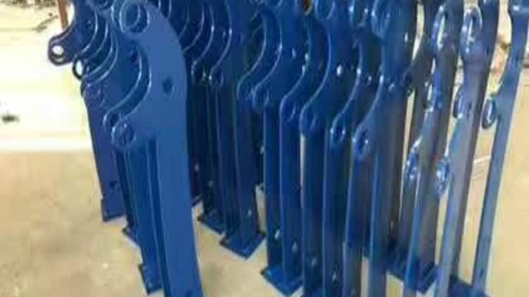
One further detail belongs to the base plate design: a stiffener. A 10 mm plate with a 100 mm square post welded to it will bend between the post wall and the anchors under moment. Adding four triangular gussets, or using a 14 mm plate, keeps the plate flat and lets the anchors take tension rather than bending. Gussets must be welded on both sides and must not create a pocket where water stands.
6. Coating Systems and Corrosion Classes
A bridge railing is a thin-section steel element in a wet, salty, sometimes de-iced environment, and its coating is what determines whether the structure still looks acceptable after ten years. Three systems dominate.
| System | Typical specification | Service environment | Expected life |
|---|---|---|---|
| Hot-dip galvanizing only | Sinkkipinnoite, average 70 to 85 micrometres depending on steel thickness | Rural and suburban inland sites | 15 to 25 years to first maintenance, longer inland |
| Duplex: galvanized plus liquid paint | 70 micrometre zinc plus 80 to 120 micrometre topcoat | Rannikko, de-iced, teollinen | 25 to 40 years with repaint of the topcoat only |
| Duplex: galvanized plus powder coat | 70 micrometre zinc plus 60 to 100 micrometre polyester powder | Architectural railings needing a specific colour | 20 to 30 vuotta, with colour retention better than liquid paint |
The galvanizing thickness clause is worth reading carefully. Coating thickness requirements are usually written as an average over the reference area with a permitted local minimum, and the requirement rises for thicker steel because the zinc reacts with the steel to form the coating and a thicker section can absorb more. A supplier who galvanizes a 4 mm rail to the same average as a 12 mm post may be compliant on the post and marginal on the rail. Specify by element, not by project average.
Duplex coatings work because the paint shields the zinc and the zinc protects the steel at any breach in the paint. The system is only as good as its preparation: a powder coat applied over a galvanized surface that was not properly chromated, swept or pre-treated will blister within a season. Where a colour is required, the sequence is galvanize, inspect and sweep, apply conversion coating, then powder coat.
7. Fabrication and Installation Sequence
Fabrication quality decides whether the installed railing is straight, plumb and quiet under load.
Cutting and drilling. Cut sections square, deburr, and drill all holes before galvanizing. Holes drilled after coating expose bare steel and are the first place rust appears.
Venting. Hollow sections must be vented so that molten zinc can enter and drain, and so that the internal atmosphere does not burst the section in the kettle. A sealed tube is a fabrication defect that a galvanizer will either reject or vent without telling anyone.
Hitsaus. Use fillet welds sized for the load, not for convenience. Weld the base plate on both sides where access allows, and use a sequence that balances heat input so the post does not bow. For Q355B in cold weather, preheat according to the qualified procedure.
Post-galvanizing correction. Some distortion after hot-dip galvanizing is normal. Straighten by controlled pressing, never by heating and quenching, which damages the coating and the steel.
Pre-assembly. Assemble bays on the ground where possible, with rails welded or bolted to posts in a jig, so that the geometry is fixed before the posts are anchored. Site welding of rails between already-anchored posts is slower, less accurate and worse for the coating.
Installation. Set the first and last posts, run a tensioned line between them, and set intermediate posts to that line. Plumb each post in two directions, grout the base, allow the grout to cure before loading the rail, and only then install the rails.
Inspection. Check plumb, spacing, rail heights, gap dimensions, coating thickness on a sample, anchor torque or proof load, and the condition of welds after coating. Record the results per bay, because a railing is accepted or rejected by its worst bay, not its average.
8. Yleisiä virheitä
Choosing spacing by eye and checking it never. A spacing that looks elegant on a drawing can exceed the post’s base moment capacity. The drawing should show the spacing and the calculation that supports it.
Using a highway guardrail post for a pedestrian railing. The two products have different design loads, different geometries and different approval routes. Substitution is a safety issue.
Dividing the moment by four. Only the anchors on the tension side resist the moment. A base plate checked with the wrong lever arm is typically undersized by half.
Drilling anchors into a crack or a cold joint. The anchor will pass a torque check and fail under a real load. Locate the reinforcement and the joints before drilling.
No movement joint at the deck expansion joint. The deck moves, the railing does not, and something has to give. Design the joint in from the start.
Galvanizing after painting holes. Any hole drilled after coating is a rust initiation point. All holes belong in the fabrication drawing.
Powder coating over unprepared zinc. Blistering and delamination within a season are the predictable result. Preparation is the whole system.
Loading the rail before grout cures. A grout that is still green cannot transfer the base moment. Waiting a day is cheaper than re-anchoring a bay.
9. Usein kysytyt kysymykset
What is the standard post spacing for a bridge railing? Between 1.5 ja 1.8 metres for most pedestrian railings. Wider spacing is possible but requires a heavier post section and a larger anchor group.
How tall should the railing be? Typically 1.1 metres to the top rail, measured from the deck. Local codes may require more on structures with a high fall risk, and the requirement should be confirmed before fabrication.
Can the railing be welded on site instead of bolted? Both are used. Site welding is common for rail-to-post connections where the coating can be repaired with zinc-rich paint; bolted connections are preferred where site access or fire risk makes welding impractical.
Is galvanizing enough for a coastal bridge? Usually not on its own. A duplex system, galvanizing plus a suitable topcoat, is the normal specification for coastal and de-iced environments.
How thick is the zinc coating? For structural sections, an average of about 70 to 85 micrometres is typical, with a minimum local value somewhat lower. The exact requirement depends on steel thickness and the standard invoked.
What anchor size should I use? M16 to M20 grade 8.8 anchors in a four-bolt pattern are typical for a 200 to 250 mm base plate. The size follows from the calculated tension, not from the plate size.
How do I check a post-installed anchor? Proof load test a sample to the specified load and record the result. Torque checking alone does not demonstrate capacity.
Why does my railing hum or vibrate? Usually wind excitation of the infill or a loose connection. Check bolt tightness and rail continuity first; if the vibration persists, the section may be too slender for the span.
Can I add a railing to an existing bridge deck? Kyllä, but the anchor design must account for the actual slab thickness, reinforcement and edge condition. Retrofit anchors near an edge are the most common source of failure.
What maintenance does a galvanized railing need? Annual visual inspection, cleaning of debris at the base, and touch-up of any coating damage with zinc-rich paint. Repainting of a duplex topcoat is typically needed after 15 to 25 vuotta, depending on exposure.
Need bridge railing fabricated and coated to specification?
Send us the span layout, post spacing, deck detail and exposure class. We will quote posts, rails, base plates and anchors as a coordinated package, galvanized or duplex coated, with inspection records per bay.
Related reading: Q235B hiiliteräksinen litteä tanko · kuumasinkitty pyöreä putki · DX51D galvanoitu nauha