 FORTSCHRITT
Verzinkter Kabelkanal: Klasse laden, End- und Installationsregeln
Verzinkter Kabelkanal: Klasse laden, End- und Installationsregeln
Cable tray is the support system that carries electrical and data cables through industrial plants, commercial buildings and infrastructure projects. It looks like a simple metal channel, but it is a structural product with a defined load class, a defined span, and a defined corrosion exposure. Choosing the wrong thickness or the wrong finish is a recurring and expensive mistake.
This guide covers tray types, load classes and how they are tested, the difference between pre-galvanized and hot-dip galvanized tray, the installation rules that determine whether the system performs, and the specification points a buyer should put in writing.
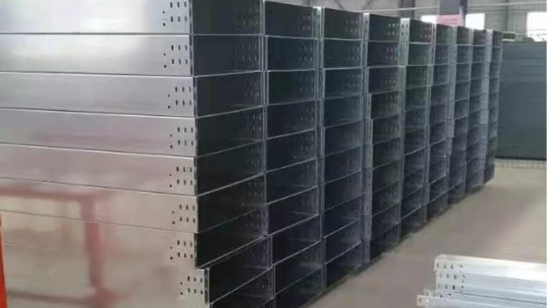
Tray Types and Where Each Is Used
Perforated tray is a channel with a perforated base and solid side walls. The perforations allow airflow, drainage and cable tying, and reduce weight. It is the most common type for light and medium cable loads in buildings.
Ladder tray has two side rails connected by rungs at intervals, with no base. It is used for heavy cable runs where ventilation and heat dissipation matter, and where cables are large and rigid.
Solid-bottom tray has a continuous base with no perforations. It protects cables from dust and moisture and is used in clean rooms, food plants and outdoor installations where debris must not fall through.
Wire mesh tray is made from welded wire, is very light, and is used for data cabling and light electrical runs in ceilings.
Channel tray is a narrow single-channel section used for small cable quantities and for drop runs.
The choice is driven by cable weight, cable type, environment and the need for access. A ladder tray is lighter per metre than a solid tray of the same load class, but it offers no protection from falling debris and no base for cable tying.
Klasse laden: What the Letters and Numbers Mean
Cable tray load capacity is normally classified by a test load per metre with a defined support span and a defined deflection limit. Common classifications in European practice run from class A (light) to class D (heavy), tested under uniformly distributed load with supports at 1.5 m or 3 m and a deflection limit of span/200 or a fixed value.
The number that matters in practice is the safe working load per metre at the actual support spacing used on site. A tray rated for 100 kg/m at 1.5 m span is not rated for 100 kg/m at 3 m span; the capacity falls roughly with the square of the span. Doubling the span quarters the load capacity for the same deflection limit.
| Class | Test load | Typische Verwendung |
|---|---|---|
| A (light) | 60 – 75 kg/m | Data, control, light power |
| B (Medium) | 100 – 125 kg/m | General building services |
| C (heavy) | 150 – 200 kg/m | Industrial power distribution |
| D (very heavy) | 250 kg/m and above | Plant rooms, heavy cable runs |
Buyers should ask for the test report, not just the class label. A tray that passes a class C test at 1.5 m span may fail at the 3 m span used in the actual installation. The report should state the span, the deflection limit and the support conditions.
Material Thickness: The Real Cost Driver
Tray is made from steel strip typically 0.8 Zu 2.5 mm dick, roll-formed into a channel and then perforated or fitted with rungs. The thickness determines the load capacity more than any other single variable, and it is the parameter most often reduced to win a price comparison.
A 1.0 mm tray and a 1.5 mm tray of the same profile can look identical from a distance, but the 1.5 mm tray carries roughly twice the load. If a project specifies class C and the supplier delivers a 1.0 mm tray with a class C label, the installation may pass inspection and fail in service.
The practical check is a micrometer at the side wall, not at the perforated base. The base is weakened by perforation and is not representative. Measure at three points along the side and at the return flange.
Pre-Galvanized vs Hot-Dip Galvanized
Pre-galvanized tray is made from zinc-coated strip (typically Z120 to Z275) that is roll-formed and punched. The zinc covers the flat surfaces, but the cut edges of the perforations and the sheared ends expose bare steel. In a dry indoor environment this is acceptable, because the zinc adjacent to the cut edge provides some sacrificial protection.
Hot-dip galvanized tray is fabricated from black steel and then dipped in molten zinc, so the coating covers every surface including cut edges and welds. The coating is thicker, typischerweise 60 Zu 85 Mikrometer, and the corrosion life is substantially longer. It is the correct choice for outdoor, Küste, chemical and food-processing installations.
| Beenden | Beschichtung | Cut edge | Environment |
|---|---|---|---|
| Pre-galvanized | Z120 – Z275 | Bare | Drinnen, dry |
| Hot-dip | 60 – 85 μm | Beschichtet | Outdoor, Küste, wet |
| Pulverbeschichtet | 60 – 80 μm | Depends on pretreatment | Architektonisch, visible |
| Rostfrei | — | Inherent | Essen, chemisch, Marine |
A common specification error is to call for “verzinkt” without stating the process. Pre-galvanized and hot-dip galvanized differ by a factor of two or more in corrosion life and by a meaningful margin in cost. State the process and the coating mass.
Installation Rules That Determine Performance
Support spacing must be taken from the manufacturer’s load table for the actual tray and load, not from a generic rule. For a class B tray carrying 20 kg/m of cable, 2 m spacing is usually fine; for the same tray carrying 80 kg/m, spacing may need to drop to 1.2 M.
Supports should be fixed to the structure, not to other services. Hanging a tray from pipework or from ceiling grid is a common shortcut that fails when the other service moves or is maintained.
Expansion joints matter in long runs. A 30-metre tray run in a building with significant temperature variation will expand and contract; if it is rigidly fixed at both ends, the tray will buckle or the supports will tear out. Provide expansion joints at intervals and leave the joint free to move.
Earthing is a safety requirement, not an option. Metallic tray used as a support for cables is often also used as part of the earthing system, and the joints must be electrically continuous. Specify the earthing method: continuous tray with bonded joints, or separate earth conductor. Do not rely on the fixing bolts to provide continuity through a painted or galvanized surface.
Accessories and System Thinking
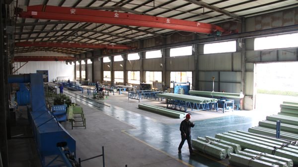
A tray system is not just straight lengths. Couplings, Kurven, tees, crosses, reducers, end caps, wall brackets, trapeze hangers, drop rods and splice plates all affect load capacity and installation time. Buying tray on price per metre and then paying premium prices for accessories from a different supplier is a false economy, because the accessories may not fit.
Order the accessories with the tray, from the same system, and confirm that the coupling is a bolted splice with a defined slip load rather than a push-fit. A push-fit coupling that pulls apart under load is a serious defect in a cable support system.
For outdoor installations, specify covers and, where required, Dichtungen. A covered tray in a coastal environment keeps rain and salt spray off the cables, but the cover must be removable for maintenance, and the fixings must be corrosion-resistant.
Quality Checks on Delivery
Check the strip thickness with a micrometer at the side wall. Check the section dimensions: Breite, side height and return flange. Check that the perforations are cleanly punched with no torn edges. Check the straightness of each length; a bowed tray will not align at the coupling.
Check the zinc coating mass on a sample, either by weighing a measured area before and after stripping, or by a magnetic gauge on the flat surface. For hot-dip tray, check the coating at the cut ends and around the welds, which is where the coating is thinnest.
Check the couplings for fit and for bolt-hole alignment. Check that the delivered accessories match the order; missing tees and reducers delay installation more than missing straight lengths, because they are usually discovered at the point of use.
Working Through a Load Calculation
A worked example makes the load class decision clearer. Suppose a plant room has a cable run of 40 metres, carrying 60 kg per metre of cable weight, supported at 2.0 m intervals, in an indoor environment.
Step one is to add the cable weight to the tray self-weight. A 1.5 mm solid tray weighs about 4 Zu 6 kg/m for a 300 mm width. The total distributed load is therefore about 65 kg/m.
Step two is to check the tray’s rated capacity at 2.0 m span. A class B tray rated at 100 kg/m for a 1.5 m span does not automatically carry 100 kg/m at 2.0 M. Using the deflection relationship, capacity at 2.0 m is roughly 100 × (1.5/2.0)² = 56 kg/m, which is below the 65 kg/m required. The tray is under-designed even though it “looks” like a class B product.
Step three is to either reduce the span to 1.5 M, raise the thickness to 2.0 mm, or select a class C tray. Reducing the span is usually the cheapest option if the structure allows additional hangers, because it uses the existing tray and only adds support steel.
Step four is to check point loads. A single large cable drum or a heavy junction box introduces a concentrated load that the uniform load table does not cover. Point loads should be checked separately, and the tray should be supported directly under the load rather than relying on the tray’s span capacity.
The lesson is that the load class label is a test result at a defined span, not a licence to install at any spacing. The installer must convert it to the actual span before ordering.
Fire Performance and Cable Behaviour
Cable tray in a fire-rated corridor or shaft is part of the fire protection strategy, not just a support. The tray material and the cable type determine whether the circuit survives long enough for evacuation and for firefighting.
Steel tray does not burn, but it conducts heat and can transmit fire from one compartment to another if it passes through a fire-rated wall without a proper penetration seal. Every penetration must be sealed with a tested system, and the seal must be reinstated if a cable is added later. This is one of the most commonly failed items in a fire inspection.
For circuits that must remain operational during a fire — fire pumps, smoke extract fans, emergency lighting, alarms — the cable and the support must be rated for the required duration. A mineral-insulated cable on a galvanized tray in a protected shaft is the conventional solution. The tray itself may need a fire-resistant coating or board in a high-risk area, depending on the fire strategy.
Where the tray carries a mixture of power and data cables, separation matters for signal integrity as well as for fire. Power cables induce noise into data cables, and the separation distance depends on cable type and on the screen. A common approach is to use separate trays or a divider, with the power and data runs at a defined distance rather than mixed in one tray.
Häufig gestellte Fragen
Can I use pre-galvanized tray outdoors? Only in a sheltered, dry location. The bare cut edges rust first, and the rust spreads under the zinc. Use hot-dip galvanized for outdoor work.
What is the maximum support spacing? It depends on load class and cable weight. Take the figure from the manufacturer’s load table for the actual load, not from a general rule.
Does perforated tray carry less load than solid tray? Ja, because the perforations remove material from the base. The reduction is typically 10 Zu 25 percent, depending on the perforation ratio.
Do I need to earth the tray? If it is used as part of the earthing system or if it carries exposed conductive parts, Ja. Confirm the method with the electrical designer.
How do I join two tray lengths? With the system’s own bolted splice plate, using the specified bolts and torques. A push-fit joint is not acceptable for loaded runs.
View hot-dip galvanized steel specifications oder Request a cable tray quote